
Announcing the ESP32 ZX Spectrum
I had a ZXSpectrum when I was growing up and now I've got a chance to recreate some of my childhood.

We’re now live on Crowd Supply! Please head over there to register your interest.
ESP32 ZX Spectrum
It looks great! Can I buy one?
Not yet - it works really well, but there are a few things to work out which are detailed below. Sign up using the button to keep in touch with progress. There will be regular updates.
What is it?
It’s an ESP32-S3 based PCB. I really wanted to try out the full color silk screen printing capabilities of PCBWay and it’s come out even better than I expected.
The keys on the keyboard are all capacitive touch pads - so they are just copper pads on the PCB. With the S3 we’ve got up to 14 touch pads and the ZX Spectrum keyboard uses 8 rows with 5 columns in each row for its keyboard.

We can recreate this using 13 touch pins, so it just about fits onto an S3. I really wasn’t expecting this to work as well as it did - but it works amazingly well. However, there are some downsides to just using an 8x5 matrix for the keys. So for the next version of the PCB I am going to add some support ICs for the keyboard matrix.
The emulator software is based off a Z80 emulator I found here. It works really well and, as you can see in the video above, it plays games and can run BASIC.
There is a very good emulator for the ESP32 called ESpectrum. I’m currently in two minds as to wether I should spend time making my board work with this software or if I should focus on the hardware.
Currently, my plan is to work on the hardware on the assumption that the current firmware is good enough - or we can get the ESpectrum firmware working on the hardware.
What are the features?
Full ZX Spectrum keyboard in glorious color
3.2 inch color 320x280 TFT display
Speaker and Headphone jack
SD Card for games/data
Lithium battery charge controller and battery connector
Dual-core XTensa LX7 MCU running at 240 MHz.
512 KB SRAM + 8MB PSRAM
2.4 GHz, 802.11 b/g/n Wi-Fi and Bluetooth 5 (LE)
3 x QWIIC connectors for peripherals (e.g. Wii Nunchuk)
USB-C connector for power/charging and firmware update
What are the challenges?
The initial proof of concept works really well. And the full color printing along with capacitive touch pads works really well.
Displays are a big challenge. I’ve decided that a 3.2 inch or 3.5 inch display will fit nicely. There are so many different manufacturers and FPC ribbon connectors. Most displays will work with 4 wire SPI but, everyone seems to have decided to use a different number of pins and pinout. It’s bonkers.
The keyboard is also a challenge. The touch matrix works really well, but it’s not as good as the old ZX Spectrum keyboard.
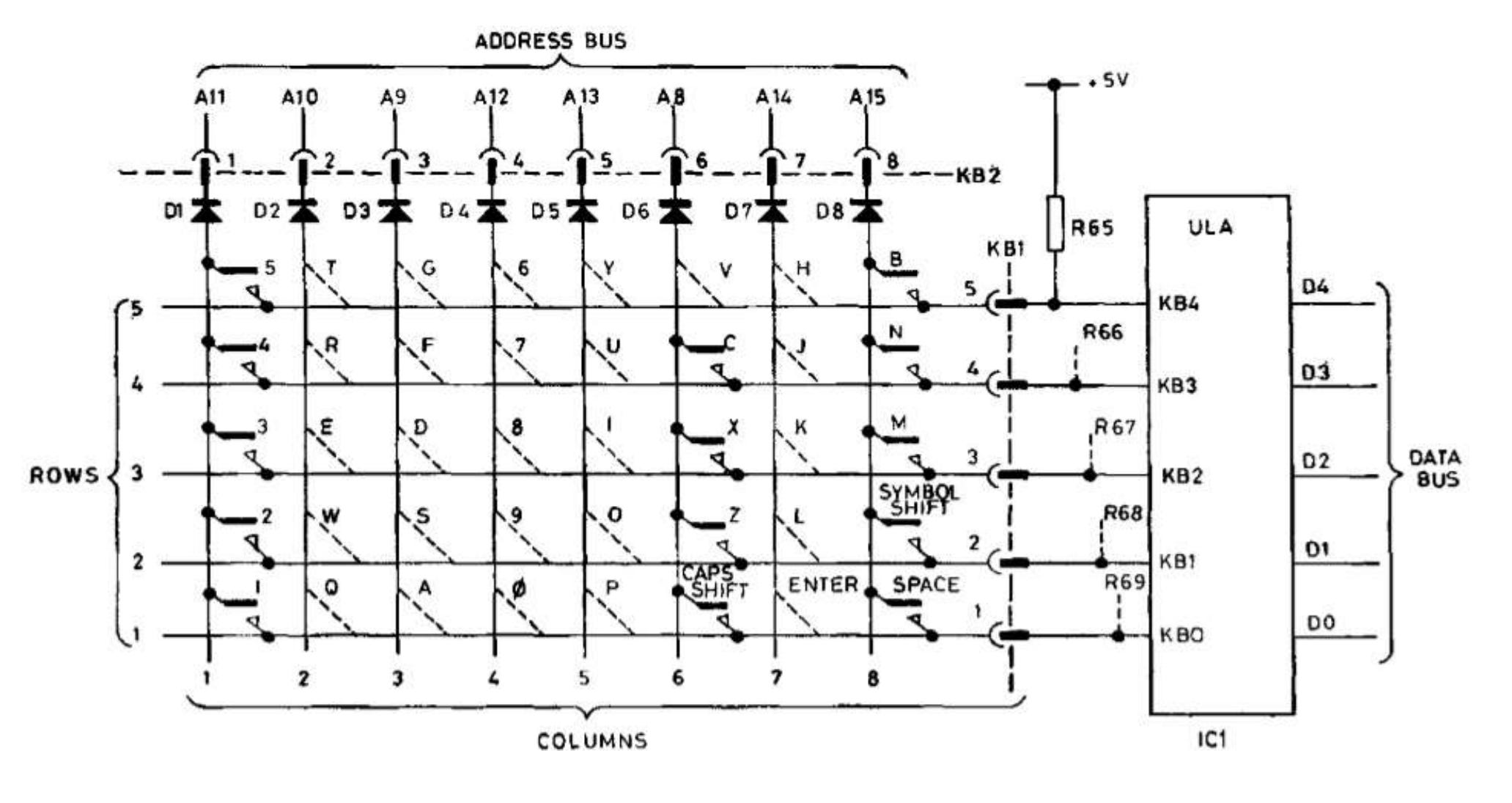
The diodes in the schematic are a key element of the circuit. They let Sir Clive scan each row individually.
With my current implementation, we get a lot of ghosting of keys. I have a cunning plan for the next version of the PCB which will eliminate this - and my initial experiments are very promising - but, I need to get another board manufactured to really see if it works.
So, if you are interested and might eventually want to buy one, please sign up for updates.
And if you know anyone else who might like one then please share this post with them - the more people who get involved the cheaper I’ll be able to do a production run.
I will be doing a follow up post and video that will do a deep dive on how everything works in the next couple of weeks - so stay tuned!
Summary of risks
I only have experience of small production runs for simple breakout boards. This is a whole new level of complexity
Keyboard limitation workaround may not work (we’ll find out in the next revision)
Identifying a display vendor with sufficient capacity and stable connector
Full color silk screen printing is still a beta technology
Component supply. This is now a lot better but any shocks to global trade could impact this
We need enough interest to justify a production run to get the price down. Small volume prototyping is great, but it’s not suitable for selling to people
It’s just me doing this. The bus count for this project is one.
Subject: Commendation on the ESP32-S3 ZX Spectrum Design
Dear Chris Greening,
I hope this message finds you well. I wanted to take a moment to express my admiration for your work on the ESP32-S3 ZX Spectrum and do some gushing to encourage you. The design truly resonates with the spirit of the original machine while incorporating modern tech elements, which is no small feat.
The placement of the 3.2 inch screen at the top is reminiscent of one of Rick Dickinson's iconic designs, and I appreciate how it allows for potential customization with a larger screen through rewiring the pins should someone want to. Merely my opinion, I like what you've done and what you are going for as it is in that upper Spectrum bar in terms of fitting the battery, screen, ports etc. up there. The addition of expansion input-output pins is a special touch that enhances the versatility of the machine. It appeals to my memory of the Usborne robot arm one could built and interface with the ZX Spectrum. The aesthetics are functional and I believe this is the beauty of your work.
Your ability to capture the essence of the original ZX Spectrum and infuse it with contemporary technology is truly exciting. It's clear that a great deal of thought and skill has gone into this project, and I am thrilled to see the result. It's a careful balance and I believe you hit it!
I wanted to extend my best wishes to you and your team as you continue your work on this project. It's inspiring to see the legacy of such an iconic machine being honored and re-imagined in this way.
Thank you for your dedication and innovative spirit. I look forward to seeing the continued success of the ESP32-S3 ZX Spectrum.
Best regards,
i guess.i like it, but lcd is too small , so would prefer some way of getting bigger lcd